As you know, all instructions and data are ultimately represented as electrical currents inside the central processing unit (CPU). Electrical current "flows" as electronic "switches" open and close in accordance with control signals generated within the CPU every time a clock pulse from the system clock is received. As these switches open and close in synchronization with the clock, instructions are performed. A computer program is actually a set of instructions that cause switches to open and close! Usually, this causes some useful processing to be done - if the program is written correctly! Other hardware, like the monitor and printer, are used to translate these electrical signals into a form that humans can understand and interpret.
On the bit level, we usually interpret the existence current to represent the binary digit 1 or the Boolean value "true". The absence of current represents the binary digit 0 or the Boolean value "false". So each computer byte can be thought of a series of "wires" connected in various ways to a series of switches which either pass or block the transmission of electrical current depending on whether a 1 or a 0 is to be transmitted.
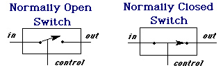
Switches, implemented as transistors, come in two basic forms, normally open and normally closed. When the control input is "1", the switch changes to the opposite of its "normal" state.
out = 0 (normally open switch, when open) out = in (normally closed switch, when closed)
These switches can be used to implement logic gates which, in turn, are used to implement the basic logical functions: NOT, AND, and OR. When combined in the correct fashion, these logic gates can be used to perform arithmetic and logic operations. So we build a computer using the most elementary components, the switches, which are used to build gates, which are used to build circuits, which eventually combine to form a complete CPU.
![]()
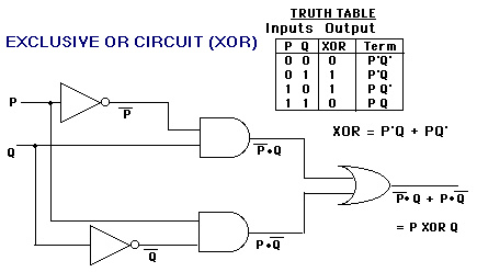
The circuit symbols used by electrical engineers and computers to represent gates are shown on the next page, along with the associated truth table, which shows what the gate outputs for each of the four possible combinations of the two inputs. Also shown is how the two basic switches shown above can be used to implement each gate in an actual circuit.

Four simple switches are required to create an OR gate:
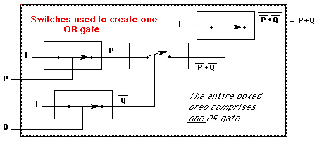
The gate circuit symbols are usually used in place of the actual switches when drawing a circuit because the gate symbols are easier and quicker to draw!
A common logic circuit frequently needed in CPUs is the equivalence circuit. When comparing two binary representations in a computer program, it is often necessary to know if they are equal. Since all data is represented internally as a series of bits in the form of one or more bytes, to determine equality, we need to look at each byte, bit by corresponding bit, and ensure that each pair of bits from the two items we are comparing are identical. If all pairs are identical, then the two bytes are equal.
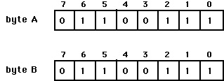
Byte A above, is equal to byte B only if bit 0 of byte A is the same as bit 0 of byte B, bit 1 of byte A is the same as bit 1 of byte B, bit 2 of byte A is the same as bit 2 of byte B, and so on. In the example above, we can see that they are equal. But how does the computer do this using gates?
To understand this, first create the truth table for a single pair of bits and determine which of the corresponding terms (expressed using the names of the inputs) are needed to write the logical expression used to express equality. [Note the use of the apostrophe (') following the input label to indicate the complement of the input bit]. The equality circuit should output a 1 (or true), only if the two bits at the inputs of the circuit are identical (both 0 or 1). The truth table looks like this:
        Inputs   Output
        ======   ======
         A  B    Result Term

         0  0      1    A'B'

         0  1      0    A'B

         1  0      0    A B'

         1  1      1    A B
Collect those terms where the result is 1 and OR them together. This is the logic function we seek to create using our logic gates.
Logical function = A'B'+ AB {determines equivalence of a single pair of bits}
Each term represents a single AND gate with the indicated bits or their complements as inputs. So to implement the function above, you need two AND gates (one for each term), two NOT gates (to get the complement of the input bits), and one OR gate (to combine the outputs of the AND gates. The output of this OR gate is the result we seek.
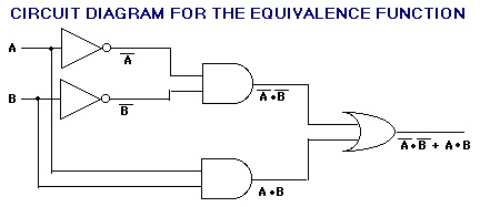
Remember that the circuit above compares only two bits of the two binary representations. To compare all the bits in the two binary items, we would need one copy of circuit above for each bit in the binary value. Each copy of the circuit would get a single pair of corresponding bits, one bit from each of the two binary values being compared. All of the outputs of each of the circuits above would be ANDed together in another circuit to determine if all the bits were the same. This "grand AND" would output a single one if every bit in a byte matches the corresponding bit in the other byte to which it is being compared.
The circuit shown below is the complement of the equivalence circuit. This circuit is also frequently encountered in computer applications, so it is given a special name: